
BNC connectors of 75 or 50 ohms impedance?
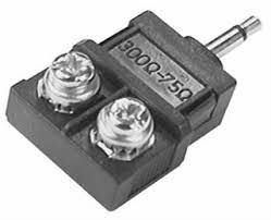
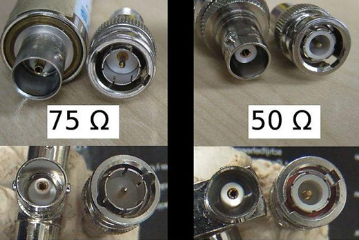 See the photos at left . They show the difference between BNC connectors with 75 ohm impedance, to be used in CCTV systems , and BNC connectors with 50 ohm impedance , which were used in older networks of computers 10Base2.
Note that in the male 75 ohm BNC connector there is no inner dielectric (the white part) and in the female connector it is smaller, or even non-existent.
Now check the male and female BNC connectors you usually buy and at the DVRs and cameras you use to install.
Are they 75 ou 50 ohms?
If they are 50 ohm, you are introducing impedance matching problems on your instalaltions, as if the impedance of cameras, DVRs and cables is 75 ohms, the connectors' should also be .
Unfortunately , I think you will find that you are using the wrong BNC connectors, with 50 ohms impedance.
Why am I saying this?
- Because I noticed that most of DVRs and cameras in the market are manufactured with BNC connectors of 50 ohm impedance ;
- Because I visited several security shops and distributors throughout Brazil and found that, except for very few exceptions, they are offering only the 50 ohms connectors;
- Because if you made a research at Ali Baba's website for some Asian suppliers of connectors, you will see that few have 75 ohm BNC connectors to offer, but worst of all is that many are unaware of what they are selling, offering 50 ohms connector for CCTV purposes and some of them don't even know the difference, offering both connectors as being of 75 ohms !!
What is the difference between resistance and impedance?
This is something that everyone be confused, because both the resistance (R) as the impedance (Z) are measured in ohms.
Below is the equivalent circuit of a connector:
Multímeters don't measure impedance Have you ever wondered why when you measure 3 ft. (1 m) of coaxial cable which has a 75 ohms impedance with a multimeter, the value read is not 75 ohm? And if you measure 30 ft. (10m) or 300 ft. (100 m) of cable, measured values will also be different (higher) . Because the mulimeter is measuring the resistance of the cable not the impedance. The longer the cable , the greater the resistance. If you take a wire gauge table, you will see that the resistance for each gauge is reported in ohms/distance. The resistance is measured by applying a DC voltage to the cable to be measured. Then it is measured the current flowing through the cable when subjected to the tension. Dividing the applied voltage by the measured current, it could be obtained the cable's resistance (Ohm's law R = V / I ) This is how a multimeter performs resistance measurements .When the connector receives a DC voltage:
- The resistance Rs is very small, almost zero;
- The inductance L is also negligible;
- The resistance of the capacitor C is virtually infinite, as with a DC voltage it will operate as an open circuit.
- The resistance Rp is obtained by measuring with the tips of a multimeter between the center pin and the connector housing and it will also be very high.
So either connector, 50 or 75 ohms, is transparent to DC voltages.
However, when submitted to an AC voltage, as a video signal, the inductance and capacitance of the circuit should be considered.
The sum of the resistance to inductance and capacitance is what constitutes the connector's impedance.
Notice that both 75 and 50 ohms connectors are similar; what changes is the inner dielectric, being the white part of the 50 ohm connector and the air in the 75 ohm connector. This dielectric gap causes them to have different capacitance, which causes the difference in impedance between them .
The characteristic impedance of a device, whether camera. connector, cable, DVR , etc. is defined as Zo , where:

Impedance matching
Why is it important that the impedance of each component of a system being the same?
To 100 % of the video signal being transmitted to the DVR, without reflection, it is necessary for the camera, DVR and cabling (cable + connectors) have the same impedance.
When connecting two devices with different impedances, one portion of the signal is reflected and returns to the origin.
Imagine an image frame sent by a camera which has 75 ohms impedance, connected to a coaxial cable with 50 ohm impedance.
![]() A part of the signal from that picture frame will be reflected and return to the camera. This reflected part of the signal will meet the video signal for the next picture frame and, having reversed polarity, will cancel part of the sign.
A part of the signal from that picture frame will be reflected and return to the camera. This reflected part of the signal will meet the video signal for the next picture frame and, having reversed polarity, will cancel part of the sign.
The graph on the left shows what happens with the video signal travelling from one device with 75 ohms impedance to another with 50 ohms. Notice as part of the signal is reflected.
Explaining the reflection in a more didactic way: When you throw a stone into a pond, the impact with the water form circular waves from the point where the stone hit the water.

When one of these waves reach the edge, it will be reflected back toward the source, reducing and deforming the waves that are still being generated by the impact of the stone.

That's what happens with the video signal when it encounters a medium with different impedance ; part of the signal will be reflected back to the source.
Reflection coefficient and return loss
The reflection coefficient (CR) can be measured by the following formula:
CR= Z1 - Z2 / Z1 + Z2
The reflection coefficient determines how much signal is being reflected . When there is impedance matching, the reflection coefficient is zero, being 1 the maximum value it can have.
For 75 and 50 ohms we have:
CR = 75 - 50 / 75 + 50 => CR = 25 / 125 => CR = 0,2
The return loss, in decibels, can be measured by the following formula:
Return loss = -20 log (CR)
This value means how many decibels the reflected signal is attenuated relatively to the original signal . The higher the attenuation of the reflected signal, the better. If the impedance is matched (two devices with the same impedance), the return loss will tend to infinity, virtually non-existent, because 100 % of the signal will be transmitted to the destination.
When CR = 0.2, the reflected signal will be with an attenuation of 13.98 dB from the original signal, a considerable value, above the acceptable limit , which is equal to or greater than 20 dB.
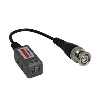
Balun, the impedance converter
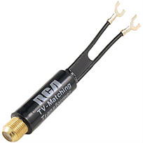
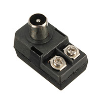
Previously , televisions used a parallel ribbon to the antenna connection. This ribbon had an impedance of 300 ohms. As they began to use coaxial cables with 75 ohms impedance to connect the VHF antenna, it was common to use 75-300 ohms baluns to connect a UHF antenna. These baluns were also used in the connection of the first video games.
Similar function is performed by the UTP-video baluns.
These baluns enable to transmit he video output signal of a camera, which has 75 ohms impedance through UTP cables, which have an impedance of 100 ohms. At the DVR side, the balun is used inverted , converting the 100 ohms impedance of UTP cable back to the 75 ohm impedance of the DVR video input.
Conclusion
The damages caused by no impedance matching are:
- Attenuation of the transmitted signal . Part of the video signal sent by the camera does not reach its destination;
- The reflected signal returns to the camera, where it will be again reflected and sent along with the new image frame to the DVR. The result is a weak and delayed image attached to the main image;
- Or, for being with the phase inverted, the reflected signal may cancel part of the signal of the next picture frame ..
Therefore, impedance matching is very important and you should ensure that all components of a CCTV system are wthe same impedance.
Return loss in cabling It's useless applying good 75-ohm BNC connectors if the chosen coaxial cable fail to keep an impedance of 75 ohms over its length. What sets the impedance of a cable is basically its dielectric, that must have a constant thickness. One easy way to test this is passing your hand over the cable surface; the diameter should remain constant, without bumps or depressions. If the cable is not rejected in this first test, check in manufacturer's specifications which is the return loss reported. Must be greater than or equal to 20 dB. If cable specifications do not inform the return loss, ask the manufacturer. If he does know that, find another cable. Of other manufacturer. This same reasoning can be used in choosing a UTP cable.
.
Source: Wikipedia

Aug/2015
Sep/2015
Wanna know when new articles will be published?
Like this article? Leave a comment!
Copyright ©2014 CCTV Institute- All rights reserved
Total or partial reproduction of any content in this website is forbidden except if expressly authorized by the author