

Using Fiber Optics in CCTV
Introduction - Part 1
As I already had commented on Video Signal Transmission, there are several ways to transmit the video signal from a camera to its destination, being fiber optics one of these ways.
Fiber Optic working principle
Coaxial and twisted pair cables transmit the video signal by the passage of electrons in metallic wires, preferably copper .
Fiber optics uses glass as a transmission medium . Video signal is converted into light pulses to be sent via fiberglass cables made at much greater distances than those achieved in metallic cables.
Fiber optic structure
RefractionTo better understand what refraction is, observe a pencil in a glass of water: Pencil will look broken. Who enjoy fishing knows, also due to refraction, fishes are not exactly where we see them.
 Fiber optics uses basic principles of physics on the reflection and refraction of light.
As we learned in high school, in optics classes, when light passes through two bodies of different densities, it undergoes refraction and / or reflection, that is a part of the light passes to the second body , but suffers refraction, and the other part is reflected as in a mirror.
To take advantage of these principles, optical fiber is composed of a transparent clear glass core surrounded by a material with lower refractive index.
Air refractive index is 1; of water is 1.33; glass that is used in the core of optical fiber is 1.5. Glass surrounding the core has a refractive index of 1.45.
And it is this difference that causes light beam undergoes refraction or reflection when it reaches the junction between core and cover that surrounds it.
In order to enjoy 100 % of the light beam being transmitted, it must undergo total internal reflection, without any refraction.
But how to achieve this ?
There is an certain angle, called critical angle, where from it all incident light will be totally reflected.
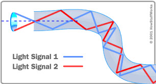
As can be seen in the figure below, from left to right , the first two light rays suffer refraction overall because they are below critical angle. Last ray of light undergoes total reflection because it had passed the critical angle.

Thus, any ray of light that reaches the boundary between the two concentric surfaces of optical fiber will be reflected, being directed to the opposite surface, where it will be reflected again. Through these successive reflections, light beam will cover all the fiber extension until it reaches the other end.
Multi-mode fiber optics
The above diagram illustrates the principle of transmission for the calling multi-mode fiber optics. It is so called because it allows the passage of multiple beams of light.
This type of fiber optics was created in the 1970s, and the first installation took place in Chicago, USA , in 1976 .
µm - micrômetroUm micrômetro é a milionésima parte de um metro. 1 µm = 1 x 10⁻⁶ m Para ter uma noção melhor do que representa um micrômetro, divida um milímetro por mil.Core of multi-mode fiber optics has a diameter of about 50 to 65 µm, coming to be thinner than a human hair, whose thickness ranges from 60 to 120 µm.
Even being so thin, this core is still thicker than the light beams transmitted through it to end up being reflected once they reach their walls.
Of course, this reflection is not ideal, because it ends up attenuating the transmitted signal, reducing its scope .
Single-mode fiber optics
To avoid the above problem, an even thinner fiber optics has been developed, with only 8 microns, called single-mode.
In a single-mode fiber, a single beam of light - hence the name single-mode - is directly guided to the other end without any reflection, allowing much greater distances to be achieved.
Multi-mode x single-mode
Multi-mode fiber optics are offered in two types of core, with 50 or 62.5 µm diameter. But despite having cores with different thicknesses, in all of them, including the single-mode type, the glass cover that surrounds the core (cladding) has the same external diameter : 125 µm for all 3 models.
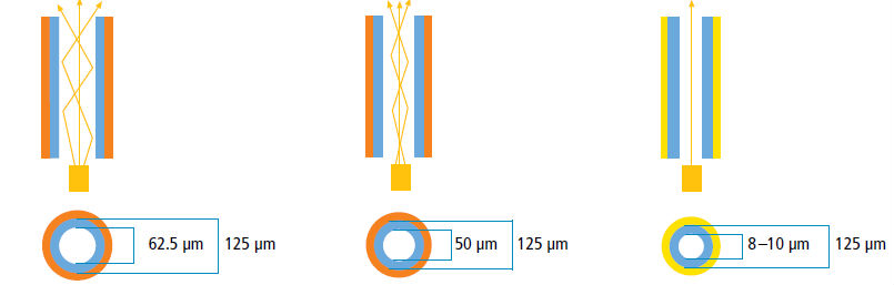
Market usually call these three fiber 62.5 / 125; 50/125 and 8/125, respectively.
In addition to the core and cover, fibers optics also have other layers:
.jpg)
Coating: Protect core and cladding
Strengthening fibers: To support traction. Usually made of aramid, prevent fiber from being damaged when passed through a conduit.
Cable jacket: It is the outer cover, to protect the whole cable.
Differences between multi-mode and single-mode fiber optic
Distance reached: About 2.5 mi (4 km) for multi-mode and 75 mi. (120 Km) for single-mode;
Light source: Multi-mode fiber uses LED diodes, that are cheaper, operating at frequencies between 850-1300 nm ( infrared ). Single-mode fiber uses laser diodes operating at frequencies from 1310 to 1550 nm;
Installation: Being much more thin, single-mode fiber requires greater precision at the seams and connectorization .
Use
Obviously, you can't connect a fiber optic directly into the camera or DVR. Special converters should be used for that.
For CCTV purposes, these converters can be:
- Video: Transmitter module transforms composite video signal coming from camera into light pulses which are again converted to a composite video signal at DVR input;
- Video + data: Transmitter module transforms composite video signal coming from camera into light pulses which are again converted to a composite video signal at DVR input. It also converts RS-485 control signal output from DVR or PTZ keyboard controller into light pulses which are again converted to an RS-485 signal at PTZ camera input;
- Multiple converters: They concentrate up to 16 video channels and data on a single fiber. In this way, it can send video signal from 16 cameras signal at a distant building to a DVR that is in another building using a single fiber optics.
OBS.: Always purchase converters compatible with the fiber optics type to be used: 62.5 / 125; 50/125 or 8/125.
Connections
All fiber optics should be connectorized in order to be used. There are several types of connectors, which should be consistent with those found in converters that you want to use.
Most common types are:
ST
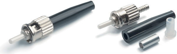 Short for Straight Tip Connector. It was developed by AT & T. Its socket, bayonet type connection, resembles a BNC connector. It 's the most widely used in CCTV .
FC
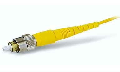 For being a screw connection, it is often used in environments subject to vibration . For many years, it was the most popular connector.
SC
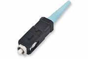 Short for Subscription Channel Connector.
LC
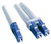 It is the newest one, used for applications where you need high speed.
At Part 2 we'll look at the advantages and disadvantages of using fiber optics instead of metallic cable.
This article was written with the collaboration of Fiberwan
May/2015
Wanna know when new articles will be published?
Like this article? Leave a comment!
Copyright ©2014 CCTV Institute- All rights reserved
Total or partial reproduction of any content in this website is forbidden except if expressly authorized by the author