
Cabling - Part 4
This is the third part of a series of articles on CCTV cabling . If you have not seen the previous parts, I recommend you to read them before, clicking in these links: Cabling Part 1 - Introduction, Cabling Part 2 - Metallic cabling and Cabling Part 3 - Coaxial cabling
UTP cabling
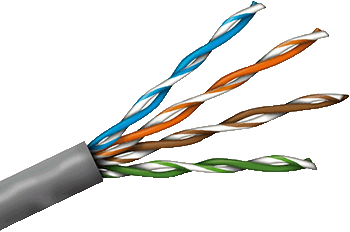 At first, video signals from a CCTV camera was set to be carried by coaxial cables, which lasted for many years, until about 20 years ago, when an American company had the brilliant idea of using UTP (Unshielded Twisted Pair) category 5e cables (4 pairs) to carry video signal of up to 4 cameras via a single cable!
The first challenge: Impedance matching
Yes, the idea seemed to be good but it had a problem: Coaxial cables are 75 ohms impedance and UTP cables, 100 ohms. This impedance mismatch could cause return loss (to know what is return loss, read this article here).
How to solve this?
With a impedance matching balun. Baluns convert the 75 ohms impedance of a coaxial cable (camera output and DVR input) in the 100 ohms impedance of an UTP cable.
Therefore, NEVER USE BALUNS WITH COAX CABLES. Just because they don't need, they already have a 75 ohms impedance.
The second challenge: The lack of shielding
The role of ground mesh of a coaxial cable is to provide a shielding against interference, with the video signal flowing in the central conductor.
The opposite is also true: Shielding also prevents signals carried trough the cable from forming an external magnetic field, which would cause interference in other nearby cables or equipment.
But how to protect an unshielded cable from interference?
The twisted pair cable
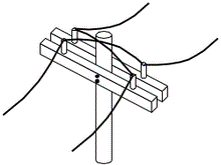 The twisted pair cable consists of pairs of wires twisted with each other in order to cancel the electromagnetic interference (EMI).
This technique was invented in 1881 by Alexander Graham Bell, the inventor of the telephone, when he realized that twisting the transmission lines on the poles helped to eliminate interference.
But how is possible to eliminate interference by simply braiding the pairs ?
Source Wikipedia
Balanced to unbalanced
In a coaxial cable, the 2 means transmitting the signal are different. One is the center conductor and the other is the mesh that surrounds it. We call this an unbalanced cable.
In an UTP cable, the 2 cables transmitting the signal are identical and twisted together. We call this a balanced cable.
Thus, the main function of a balun is not to convert the 75 ohm impedance of coaxial cable to the 00 ohm impedance of an UTP cable and vice versa. Its most important function is to convert a balanced system (twisted pair cable) to an unbalanced system (coaxial cable) and vice versa . Hence the name:
BalUn - Balanced to Unbalanced
Which is the advantage of using a balanced cable?
In a balanced cable, signal is also balanced. It is divided into 2 equal parts, one of which is sent inverted.
For example a video signal of 1 volt peak-to-peak at the output of a camera is divided into 2 parts: A 0.5 Vpp exiting the + terminal of the balun and the other half is inverted, being with - 0.5 Vpp , which leaves the - terminal of the balun.
The balun + terminal is connected to the darker color of a twisted pair.
The balun - terminal is connected to the light-colored cable (or striped, or white) of a twisted pair.
The advantage of this is that the electromagnetic fields formed by the two signals that run through the pair, being of inverted polarity, cancel itself, forming a shield which prevents the cable from causing interference to other nearby cables or equipment.

Besides that, due to the cable being braided, any interference or external noise will reach the two signals with the same intensity.

Upon arriving at the other end, the negative half of the signal is again inverted and added to the positive half being the signal back to 1 Vpp .
As the negative half of the noise is also inverted with the video signal, when the two halves of the signal are added, noise is canceled.
That is, the reversal polarity signal of the two halves forms a shield against external interference.
It's then explained how the use of baluns for twisted pair cables can form a shielding similar to that of a coaxial cable .
Ground loop
As explained in 7 things you need to know about power supplies for CCTV, the unwanted ground loop effect occurs when there is a difference of potential between the ground reference of a camera and a DVR .
This generates an AC current that flows between the camera and the DVR ground and the mesh of the video cable, forming a ground loop, whose symptoms are those horizontal bars that are going through the screen:
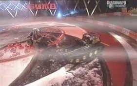

However, as the twisted pair takes only two balanced signals, there is no path to ground between the two baluns.
So as it doesn't close a loop, there is no place to the ground loop effect on an unshielded twisted pair cable.
Do not use shielded twisted pair cable!
Video baluns were designed to be used with UTP cables, or unshielded cables.
Therefore, don't use FTP, STP or any other type of shielded twisted pair cable with video baluns.
Simply because the cable shielding will form a dirt road between the camera and the DVR, closing the loop, which will allow the occurrence of an undesirable ground loop effect.
But, if by chance you have to use a shielded twisted pair cable, connect just one side of the shield to the ground (DVR or camera side) , not both , to avoid creating a loop.
Also never leave the shield disconnected from both sides. Without a grounding point shield will act as a deflector for the magnetic field formed in the cable, extending its reach, which can cause interference with nearby cable or equipment .
Centralized power supply
As noted above, any noise picked up by the cable is canceled when one half of the signal is again inverted to be added to the other half.
At camera's side when video signal passes through the first balun, it's divided into two equal halves, with reference to the ground of the BNC connector in the input balun.
At the other end , when the signals are added again , it's taken as a reference ground the BNC connector of output balun .
The problem is that if the ground of the two sides aren't at the same potential, noise will not be fully canceled.
In the example below, there is a difference of 0.1 V between the grounds of camera and DVR.

Thus, to a shielding against interference of a twisted pair cabling with baluns function properly, ground reference of two ends must be at the same potential.
So it is extremely important to use a centralized power supply to ensure that camera and DVR are in the same ground potential.
Image resolution and bandwidth
When baluns for CCTV were invented , more than 15 years ago, horizontal resolution of most cameras was about 330 HTVL, occupying a bandwidth of only 4.13 MHz .
However, when the horizontal resolution of video cameras began to increase, the required bandwidth increased proportionally .
For example, for a 420 HTVL camera it is necessary a 5.25 MHz bandwidth; for 600 HTVL , 7.5 MHz .
The chart below shows the bandwidth required for each horizontal resolution value :
.png)
The problem is that this increasing of resolution meets physical limitations of the baluns .
Let's take as an example the typical specifications of a common passive balun here, manufactured by Chinese companies:
.png)
In the second and third lines, it is informed that the frequency response is 0-6 MHz for a maximum distance of 300m.
At most a 6 MHz bandwidth? So baluns liabilities will cut any resolution above 480 HTVL!
.png) This means that if you intend to make a CCTV installation with passive baluns and twisted pair cable, there is no reason using cameras with resolutions higher than 480 HTVL because any resolution above that will be filtered by baluns.
This means that if you intend to make a CCTV installation with passive baluns and twisted pair cable, there is no reason using cameras with resolutions higher than 480 HTVL because any resolution above that will be filtered by baluns.
But does this limitation only occurs with these Chinese baluns or are they all like this?
To clarify this question, I sought the specifications of an American balun manufactured by the company that invented these baluns for CCTV.
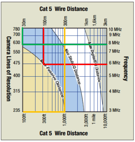 This manufacturer prefers to show frequency response x distance through a graph where at " Max Passive Distance " curve , we have:
- In red, up to 100 m distance to 480 lines of resolution;
- In green, for a resolution of 600 HTVL, only 30 m!
- In yellow, for a distance of 300 m, only 235 TV lines of resolution!
That is, for higher resolution cameras , you can not use UTP cables with passive baluns for long distances.
When this kind of balun was invented, it was Ok as the resolution of the best image sensors was no more than 480 HTVL.
The solution would be to use active baluns at the reception, close to the DVR, and passive baluns close to the camera where become valid the results showed in the central curve of the chart above, where we have:
- For 480 lines of resolution, 400 m;
- For 600 HTVL, 300 m.
- For 800 HTVL, about 150 m.
How an active balun corrects the loss at high frequencies?
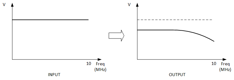
Passive baluns
In passive baluns, losses due to the electrical resistance in the cable attenuates the level of the video signal. In addition, higher frequencies suffer greater attenuation due to the capacitive effect of the cable and the limitations of the balun itself.
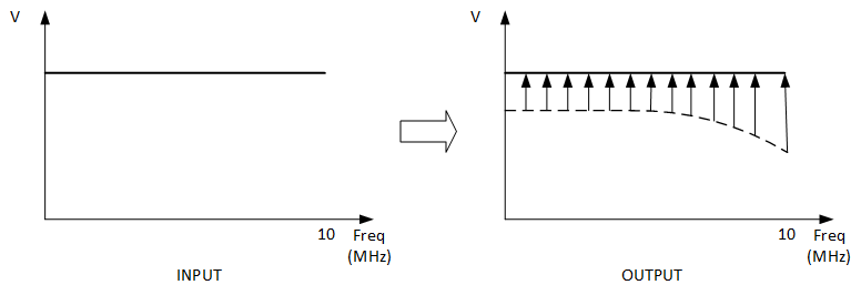
Active balun at reception
When we put an active balun at the reception, the video signal level are equalized, that is, the level of higher frequencies suffer greater amplification than the lower frequencies, causing the signal being back to the same level across the frequency spectrum.
WARNING: IF ONLY ONE ACTIVE BALUN IS BEING USED, IT MUST BE THE RECEIVER
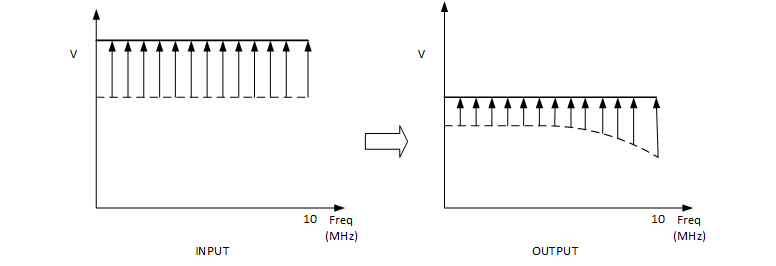
Active baluns at both sides
Can be achieved greater distances using baluns active both in transmission and in reception because the active balun transmission already raises the signal level before transmitting it, thus allowing a greater attenuation in the cable (longer cable length) and active balun at the reception equalizes the received signal
Some tests I did
I was wondering if this distance and resolution limitations for passive baluns was really that critical.
So I picked up a pair of that Chinese passive baluns, exactly those of the above specification and tested them for the frequencies from 0 to 10 MHz (up to 800 HTVL ) with 100 , 200 and 300 m of a good quality UTP CAT 5e cable, composed by rigid wires of pure copper .
UTP CABLES Always use UTP cables formed by rigid wires of pure copper . Copper-clad aluminum cables are not suitable for applications in CCTV . UTP formed by flexible wires are not suitable for installation in ducts because they are more flexible. They should only be used in patch cords to connect the computer to an LAN outlet . Results I've got were a little better :
- For 100 m of UTP cable up to 800 HTVL
- For 200 m of UTP cable up to 280 HTVL
- For 300 m of UTP cable up to 150 HTVL
What can be concluded :
ALWAYS USE GOOD QUALITY UTP CAT 5e CABLE,S, MADE OF PURE COPPER
NEVER USE PASSIVE BALUNS FOR DISTANCES ABOVE 100 M!
In tests with an active receiver balun I could get a 800 HTVL resolution with up to 350 m UTP cable.
Powering cameras through UTP cables
As each UTP CAT 5e cable has 4 pairs, you can also send power to the camera via UTP cables.
In this case , you can not send signals from up to 4 cameras via a single cable. It will be needed one UTP cable for each camera.
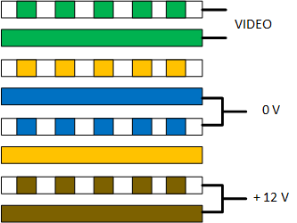 In order to also send power, it is made the following connection:
- Video signal is connected to the green pair ;
- Joins the 2 wires of blue pair to connect the negative of power supply;
- Joins the 2 wires of brown pair to connect the positive of power supply.
As each wire has a 24 AWG gauge, joining a pair to carry the power will double the wire gauge ( 2 x 24 AWG), and thus achieving twice the distance.
In this case , it uses a special balun and a RJ-45 connector on the UTP cable.
.png)
With that wire size (2 x 24 AWG) ,it's possible to feed cameras up to the following distances with a 12 VDC power supply:
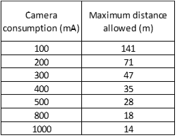
For a camera that consumes 300 mA as one with a 30 m IR, power can go only up to 47 m away.
It seems too little, but it is the correct calculation, as it takes into account the specifications of camera manufacturers, which stipulate that a camera must be powered with 12 V plus or minus 10 %, ie from 10.8 to 13.2 V.
Therefore , cameras should not be supplied with voltages lower than 10.8 V. Below this voltage camera's life may be compromised and their characteristics such as signal-to-noise ratio, resolution, sensitivity, etc., can be affected. This calculation will be explained in the next article in this series, which will be about power cabling.
TIP: Two cameras video signals + power on the same UTP cable If you have two cameras installed very close, on the same pole, for example, you can receive the video signal and feed these two cameras with a single UTP cable.Just use the orange pair, which was vacant, for the video signal from the second camera .The problem is that you will need to make an adjustment, using 2 pairs of video baluns (no power) and make the power connection manually . Another problem is that as now two cameras are being fed, you must add the current consumption of these 2 cameras to determine the maximum distance allowed.For example, for 2 identical cameras that consume 300 mA each, the maximum distance will be halved. Instead of 47 m, it will be only 23.5 m .
Powering cameras far away
You can extend these distances sending supply voltages higher than 12 Volts and using tension reducers video baluns at the other end .
There baluns are normally standard rack size for up to 16 cameras andcome with internal 24 or 36 volts power supplies. The maximum distances achieved will depend on how each manufacturer designed the reducing power supply , but they will be close to these:
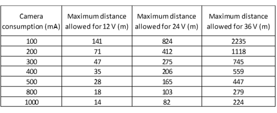
The only problem is that I haven't seen so far any of these sets of power + video baluns using active baluns, only passive ones.
Being that that would be useless to extend this maximum distance to power the cameras if maximum distance allowed for the video signal with passive baluns, without loss of resolution, is only 100 m...
Connecting video baluns
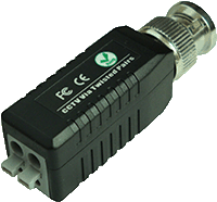
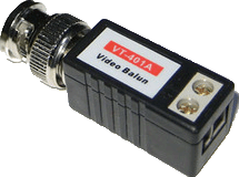
UTP video baluns use various types of connection: Pressure terminals , screw terminals and even RJ-45 connectors.
.png)
Problem is that none of these connection types is suitable for outdoor use, as they are not immune to moisture or dust.
Whereas about 80 % of the calls for service are related to cabling problems (bad contact, broken connections, etc.), it is highly recommended to accommodate baluns that are installed outdoors in enclosures with IP 66 protection.
HD Analog Cameras
HD analog cameras, of HD-CVI, HD-TVI and AHD echnologyies, use a much higher bandwidth than the 10 MHz used by a 800 HTVL resolution of an analog camera.
Depending on the technology, required bandwidth can exceed 50 MHz.
Therefore, it is necessary to use HD baluns, which are specially designed for these technologies.
They are more expensive than conventional passive baluns and maximum distance reached is about 200 m.
Up to now , there aren't active baluns for these HD technologies, only passive.
Conclusion
The use of UTP cables with baluns to send video signals is an alternative to coaxial cables.
You cannot say that one solution is better than the other; it will depend on the application, the distances involved, etc.
The important thing is to weigh all the variables involved (cost of each solution, infrastructure conditions, etc.) to choose the most appropriate solution for each situation, the one with the best cost / benefit.
Part 5 - Design the cabling to power cameras(soon)
Apr 2016
Wanna know when new articles will be published?
Like this article? Leave a comment!
Copyright ©2014 CCTV Institute- All rights reserved
Total or partial reproduction of any content in this website is forbidden except if expressly authorized by the author


